Adam Zygmontowicz and Jennifer Dworak
Department of Computer Science & Engineering Southern Methodist University Dallas, Texas, USA
Al Crouch and John Potter
ASSET InterTech, Inc. Richardson, Texas, USA
Abstract—Today’s chips often contain a wealth of embedded instruments and data, including sensors, hardware monitors, built-in self test (BIST) engines, and chip IDs, among others. IEEE P1687 was specifically designed to provide access to such instruments in an efficient manner, and some companies are already implementing the proposed standard on their chips. However, while instruments provide valuable information and features to authorized users who need to harness them for test, debug, diagnosis, and possibly counterfeit detection, it may be desirable to restrict unauthorized access to certain instruments through the P1687 network. Previous work proposed replacing some of the segment insertion bits (SIBs), which add scan path segments in a P1687 network, with locking SIBs (LSIBs). LSIBs use the data that is naturally scanned through the network as keys to hide instruments from attackers. However, that previous work did not investigate many of the techniques and structures that can be used to significantly increase the time an attacker is likely to need to unlock LSIBs and gain access to hidden instruments. In this work, we explore some of these techniques and show how simple modifications to a P1687 network protected with LSIBs can significantly increase the difficulty an attacker faces in attempting to access protected instruments.
Keywords—DFT; P1687; IJTAG; security; scan; lock; trap; LSIB
I. INTRODUCTION
Over the last decade there has been a proliferation in the number and type of on-chip embedded instruments. Some examples include memory and logic built-in self-test controllers (MBIST and LBIST), trace buffers, temperature and delay sensors, voltage and frequency domain controllers, and I/O configuration hardware. They are valuable tools during test, debug, and diagnosis, as well as when portions of the chip (such as the SERDES I/O) need to be configured.
The proposed IEEE standard P1687 was started to enable efficient access to these instruments. It allows the scan chain that accesses instruments to be dynamically reconfigured by opening new chain segments. Unlike IEEE 1149.1, which is instruction-based, this dynamic reconfiguration is controlled by the data shifted through the scan network. Although P1687 supports multiple hardware architectures through its description language, generally the network reconfiguration is controlled by segment insertion bits (SIBs) that allow additional areas of the scan network to be accessed when the correct value is clocked into the SIB’s Update cell.
Although companies may not object to end users accessing some types of instruments, access to others, such as sensors, trace buffers, scan-dump, and configuration hardware, may be a threat to on-chip IP or safety. Information such as chip IDs and encryption keys should also be made inaccessible to attackers. An efficient method of protecting instruments in a P1687 network from unauthorized access is needed.
Often, an attacker with no specific knowledge of the network will scan random data or specific patterns (e.g. walking a one) through it and will observe the effect on circuit behavior and data captured in the scan cells. In a standard P1687 network, this strategy will allow the attacker to quickly open all SIBs and map the network architecture, obtaining access to all embedded instruments attached to the network.
To prevent this, Locking SIBs (LSIBs) were introduced in [1]. LSIBs use data that is naturally scanned through the network as key bits that must be set to the correct value for the corresponding LSIB to open. As the scan chain length and the number of key bits increases, the expected time required for an attacker to unlock an LSIB increases dramatically. For example, with a scan length of 5120 scan cells and a key size of 48, unlocking an LSIB with pure random guesses is expected to take more than 9000 years on average.
That paper also introduced the concept of Trap bits that, if tripped by an attacker, can prevent him from opening an LSIB even if the correct key is found, and it briefly considered the effect of hierarchical network architectures on LSIB security. (Keys are enablers; Traps are disablers.) However, there are many optimizations to a secure P1687 network protected by LSIBs that were not explored in that paper. For example, responses that an attacker receives from his manipulation of the network can provide misleading information that encourages the attacker to pursue fruitless exploration paths. Other optimizations may reduce or eliminate the transfer of information to the attacker. In this paper, we describe some of these methods and explore their ability to increase the expected time for an attacker to access hidden instruments.
II. RELATED WORK
Design for Testability (DFT) hardware, especially scan chains, are well-known avenues for attackers to gain unauthorized access to internal chip infrastructure. In the case of JTAG ports, this often involves an attacker shifting undocumented instruction encodings into the chain and looking at the chip response. Scan chains may also be harnessed by unauthorized users to capture and read out internal circuit states and break encryption hardware (e.g. [2]–[4]). Thus, some chip providers fuse off the JTAG port after test and before the chip is shipped. Unfortunately, the port can then no longer be used for debug, configuration, or diagnosis.
Many researchers have proposed other methods of protecting the JTAG port and scan chains from attack. Some methods use challenge-response pairs along with hashes or encryption algorithms (e.g. [5]–[8]). Others reorder the scan chain if the first k-bits shifted in don’t correspond to a pre-chosen key (e.g. [9], [10]). Other methods disguise chain data by changing it with inversions or XORs [11]–[13]. [14] aims to protect a scan chain by requiring several keys to be scanned into the chain over several cycles during a test initialization phase. The authors of [15] investigated the effect that on-chip DFT hardware, such as response compaction, X-masking etc., could have on the information made available to an attacker and the need for countermeasures. Finally, [16] proposes an open circuit deadlock (OCD) cell which inserts an open into the scan chain if a SecureRST signal has not been asserted by key checker function hardware.
Our paper builds on the LSIBs introduced in [1], and shows how relatively inexpensive modifications to the P1687 scan network can make the feedback obtained by an attacker less useful. We investigate the impact that honeytraps, naturallyopen LSIBs, and switching LSIBs can have on the expected time required for an attacker to find a hidden instrument behind a particular LSIB. We will show that these techniques can have a dramatic impact on the time required.
III. LOCKS, KEYS, AND TRAPS IN P1687
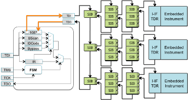
Figure 1 shows a hierarchical P1687 scan network that allows access to embedded instruments by opening and closing SIBs. When a SIB is open, it allows access to a new segment of the scan network. When the SIB is closed, it bypasses that segment, making the overall scan path shorter.
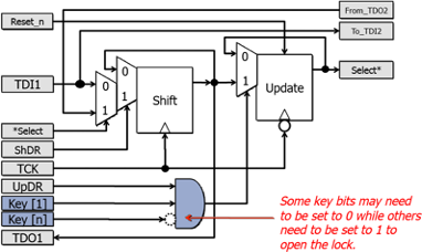
[1] Figure 2 shows a schematic of a Pre-LSIB [1] (that inserts the new scan path before the shift bit). When a logic 1 is placed in the Update Register, the Select* line is asserted. This enables the scan chain elements in the new segment and allows the first mux to select the signal FROM_TDO2 as the data clocked into the Shift cell, effectively adding the new segment to the scan chain. An LSIB can be created from a normal SIB by gating the Update signal, UpDR, with a set of key bits (shown in purple). The key bits correspond to values in other predefined scan cells in the P1687 network. Opening an LSIB requires not only clocking the correct value into the Update cell, but also scanning the correct data into the key bits in the chain. (Note that although Figure 2 shows a set of key bits AND’ed together that would appear on every chip instance, it is possible to use E-fuses or programmable logic to make the conditions required for an LSIB to open vary from one chip to another. This is similar to a method of storing a key suggested in [16]. In that work, an open circuit was inserted in the scan chain when an appropriate key was not entered.)
Although P1687 does not mandate that an IEEE 1149.1 TAP controller drive the scan control signals, in many cases an 11491.1 TAP is likely to be used, and an attacker will need to utilize the 1149.1 state machine to execute capture, shift, and update functions. The rest of this paper will assume control of the P1687 network through the 1149.1 TAP. This means that multiple clock cycles are required to execute guesses that involve filling the chain with random data, assert UpdateDR (Update Data Register), and then check the length of the chain.
Finally, [1] also introduced Trap bits. A Trap bit asserts a Trap-Enable signal when the trigger value is written to the bit’s Update cell. For example, a positive logic TrapEn signal may be inverted and fed into the AND gate shown in Figure 2 to keep the target LSIB that hides an instrument from ever opening. The Trap Bit logic contains internal feedback so that once the Trap is asserted, it can only be de-asserted by asserting reset. If the trap bit is reset using the 1149.1 Test Logic Reset (TLR) state, this effectively doubles the expected time for an attacker to open an LSIB by requiring a pass through the TLR state at the start of every guess to clear all possible previously tripped Traps.
IV. OBFUSCATION STRATEGIES
In [1], it was assumed that an attacker would enter a random vector into the scan chain as a “guess” to try to open an unknown LSIB. Without knowledge of the network, a random guess is likely to be among the best choices, as it reduces bias. The network interrogation process would check the chain length after each guess, and an increase in length would indicate that a new chain segment had opened—potentially providing new access to additional instrument TDRs (test data registers), LSIBs, or keys. Leaving aside the possibility of power analysis, imaging, or physical delamination of the part (which are beyond the scope of this paper), the attacker is faced with a black box problem and limited to observing data exiting the chip pins. The most visible feedback is to note a change in the length of the scan path. Here, we propose reducing the information present in such feedback by making it complicate the attacker’s strategy or by removing that feedback entirely.
A. Providing Unclear Positive Feedback: Honeytraps
Opening an LSIB and observing an increase in chain length is likely to be seen as a positive result by an attacker because more of the network is available. We can take advantage of this by including honeytrap LSIBs (HTLSIBs) in the network, where a HTLSIB is a network element that encourages the attacker to repeatedly make poor decisions that prevent him from accessing hidden instruments. (The “honeytrap” term arises from the fact that the approach is similar to the honeypots used in internet security to counteract attacks [17]).
HTLSIBs could consist of an LSIB that does not provide access to any hidden instruments or keys, but disables a second LSIB whenever the HTLSIB is open. For example, the Select* line that enables a new scan segment accessible through the HTLSIB may be inverted and fed into an AND gating the UpdateEn signal of a different LSIB (such as the AND gate in Figure 2), preventing the second LSIB from opening whenever the HTLSIB is open. Once the attacker opens the honeytrap, he is likely to want to continue opening it on each guessing attempt because it provides access to a portion of the network that may contain key bits, LSIBs, etc. Instead, only using such guesses ensures that he will never open the target LSIB.
For the HTLSIB to help prevent or delay the opening of a target LSIB, it should be found by the attacker first. If the target LSIB is opened first, disabling features of the HTLSIB become inconsequential. The primary driver for increasing the expected time required to open an LSIB is key size, so the number of key bits for the HTLSIB should be low to increase the chances of it being opened early. One could argue that a clever attacker will be able to guess that a HTLSIB is a trap by using the approach specified in [1] to find the exact key and trap bits that relate to the newly opened HTLSIB. An unusually small number of key bits or a small scan network behind the HTLSIB could indicate that this LSIB is indeed a
trap and opening it should be avoided. However, we can make this seemingly clever attack strategy less effective if we make some apparent HTLSIBs necessary to open target LSIBs by, for example, placing key bits behind them. Then an attacker who avoids opening all possible/likely HTLSIBs will not be able to successfully access hidden instruments either.
The potential use of HTLSIBs increases the search space that an attacker must explore. As each LSIB is opened, he must consider that it could be required to be open for any future progress to be made. However, opening it could also make it impossible to make future progress. The number of scenarios grows exponentially as more LSIBs are discovered.
Consider the case of a single potential HTLSIB where the initial chain length is n, and the chain length behind the potential HTLSIB is m. Assume the attacker checks the chain length by shifting in a distinctive d-bit pattern and observing when it exits the chain. Also assume the attacker has already determined which bits are the key bits to open the HTLSIB and where the new chain is inserted when it’s open. Then, the cost of a guess to open a target LSIB (i.e. an LSIB that hides an embedded instrument and has not yet been found by the attacker) when the attacker lets the HTLSIB remain closed is:
Cost of guessHTLSIB_closed = 10 + 2n + d (1)
This is the same as the equation from [1] for the cost of a guess when opening an LSIB in which Trap bits may be present in the network. It includes resetting the circuit (to untrip any Trap bits sprung on the previous guess) and going through the RunTestIdle, SelectDR, CaptureDR, and ShiftDR cycles of the 1149.1 state machine (5 cycles). Note that this assumes that the P1687 instruction remains in the instruction register after Reset. If it does not, a sequence of instruction load cycles will need to be added. This is followed by shift cycles to shift in the new pattern and UpdateDR to try to open the target LSIB with the current random guess (n+1cycles). This is followed by traversing the state machine from RunTestIdle through ShiftDR (4 cycles) and then shifting n+d bits through the chain to check the chain length.
If the attacker assumes the newly-opened LSIB is not a HTLSIB and should be opened first, the cost of a guess is:
Cost of guessHTLSIB_open = 15 + 3n + 2m + d (2)
This includes (6+n) cycles to open the HTLSIB, ending in UpdateDR, followed by (4+n+m) cycles to go from
RunTestIdle through ShiftDR and then shift n+m bits through the chain. An UpdateDR cycle is then used to try to open the second LSIB, and the attacker must go from RunTestIdle to ShiftDR to allow him to check the chain length by shifting (probably) n+m+d bits through the chain. Note that, to be safe, for the same random guess of n bits in the original chain, the attacker must try opening the target LSIB twice, once with the potential HTLSIB open and once with it closed. The cost of a guess becomes the sum of the two:
Cost of guessone_HTLSIB = 25 + 5n + 2m + 2d (3)
Similarly, if two possible HTLSIBs have been opened before the target LSIB is found, the number of cases the attacker must consider is at least 4 per guess: 1) both HTLSIBs closed; 2) HTLISB1 closed; HTLSIB2 open; 3) HTLISB1 open; HTLSIB2 closed; 4) both HTLISBs open. (If the attacker believes that a
honeytrap may need to be opened, key bits behind it set, and then the honeytrap closed again, then the number of cases he needs to consider increases by three.) Assuming he only considers the first four cases, and the number of bits behind the second honeytrap is j, the cost of a guess becomes:
Cost of guesstwo_honeytraps = (10 + 2n + d) + (15 + 3n + 2m + d) +
(15 + 3n + 2j + d) + (20 + 4n + 3m + 2j + d)
= 60 + 12n + 5m + 4j +4d (4)
(This assumes the second LISB is opened after the first on another pass when both LSIBs are opened because their key bits are mutually exclusive. If they can be opened on the same pass, the cost is less.) If the attacker uses the same random values for the n, m, and j bits for each set of 4 tries, and if there are k key bits and t trap bits in the main chain associated with opening the target LSIB, then the expected cycles to open the LSIB with two potential honeytraps, of which only one combination of open honeytraps will work is: Expected Time(unlock LSIB w/2 honeytraps) =
(60 + 12n + 5m + 4j +4d)(2k+2t+1) (5)
This assumes the attacker must open both honeytraps before he can open the target LSIB, but it does not include the cost of finding the two honeytraps and the key bits that control each. The effect of the trap bits was doubled because the trap had to remain unset for two passes before a guess to open the target LSIB was made. (We assume that traps disable LSIBs from opening on subsequent cycles, not the current one.) If some other combination of honeytraps must be open to open the target LSIB, the time to open the target LSIB could be less because it could potentially be opened on earlier tries when both honeytraps have not yet been found and because there will be fewer opportunities to trip the trap. Also note that this equation assumes pure random guessing (i.e. guesses may be repeated). If the number of key bits to open an LSIB were equal to the length of the chain minus 1 (for the LSIB itself), then an attacker who applied random guesses without repetition could cut the expected time by approximately half. (which could be counteracted by adding another key bit to the chain.) However, when additional bits that are not key bits for an LSIB are present in the chain, the advantage of not repeating guesses is less because the different guesses may vary only in non-key bits until the expected time approaches the initial pure-random case. In this paper, we assume that the key bits only correspond to a fraction of the total chain length and thus use the simplified analysis of pure random guesses.
B. Providing Negative Feedback: Closing a Chain In the previous section, honeytraps provided positive feedback by opening new areas of the chain. The reverse of that would be to insert LSIBs that are initially open on resetting the circuit, but close when correct key values are scanned into the chain. This could be disturbing to an attacker because it would reduce his access to potential key bits, instrument TDRs, etc. However, we can make this naturally open LSIB (NO LSIB) disable the target LSIB in its open state. An attacker would need to overcome his natural inclination to not reduce the size of the scan network to open the target LSIB. Furthermore, all NO LSIBs would not need to disable other SIBs in their open state. To make the attacker’s job harder, some NO LSIBs could disable other LSIBs in their closed states instead. Because an attacker would not know which condition may be needed to open a target LSIB, he needs to try both.
Assume that the base chain length is n and the chain length behind the NO LSIB is m. The cost of an attempt when the LSIB is left open is:
Cost of guessNO LSIB_stays_open = 10 + 2(n +m) + d (6).
This is similar to Equation 1. The difference arises from the fact that the length of the chain we are scanning through is longer when the LSIB is open, and the attacker needs to scan through the expanded segment. In contrast, the cost of a guess if the attacker first chooses to close the LSIB is equal to:
Cost of guessNO LSIB_closed = 15+3n + m + d (7)
This is similar to Equation 2. The difference arises from the fact that the attacker must only make one pass through the longer chain containing the extra m bits instead of two. Thus, the cost of making a guess when both options are tried is:
Cost of guessone_naturally_open_LSIB = 25+5n + 3m + 2d (8)
Note that this is larger than Equation (3) by m. Thus, the cost to an attacker is larger with NO LSIBs, than with honeytraps. Furthermore, an increase in cost is present on the very first pattern he tries, and all subsequent tries before finding the first NO LSIB, because the scan path through the network is longer.
As expected, increasing the number of NO LSIBs to two significantly increases the cost if all four combinations are tried. Assume the second NO LSIB has j scan cells in its expanded segment. Then, the cost of a guess if the attacker tries all combinations of open/closed LSIBs (and if he closes the first LSIB before the second if both are to be closed) is:
Cost of guess two NO LSIBs = [10+2(n+m+j)+d] +
[15+3(n+m)+j+d] +[15+3(n+j)+m+d] +[20+4n+m+2j+d]
= 60 + 12n + 7m + 8j + 4d (9)
Comparing Equation (9) to Equation (4), it is more expensive for an attacker to make guesses with NO LSIBs than with honeytraps for the same number of bits in each chain segment. The difference arises from the fact that the chain is longer for a greater percentage of the time with NO LSIBs. If the attacker uses the same random choice of values for the n, m, and j bits for each set of 4 tries, and if there are k key bits and t trap bits associated with opening the target LSIB, the expected time in cycles required to open the target LSIB with two NO LSIBs is: Expected Time(unlock LSIB w/2 NO LSIBs) =
(60 + 12n + 7m + 8j +4d)(2k+2t+1) (10)
This assumes the attacker must close both NO LSIBs before he can open the target LSIB, but it does not include the initial cost of finding the two NO LSIBs and the key bits that control each. As before, if some other combination is required, then the expected time to open the target LSIB may be less because it could potentially be opened on earlier tries when both NO LSIBs have not yet been found and because there will be fewer passes through the chain on which a trap may be set.
C. Providing No Feedback: Hiding an Increase or Decrease in Chain Length
So far, we have assumed an attacker will use the chain length as an indicator of whether a new area of the chain has been opened (or closed). A slight modification to the design of an LSIB can very inexpensively remove even this amount of information. Consider Figure 3, which contains an example schematic for a “Switching LSIB” (SLSIB). Instead of opening or closing a single segment of the chain, it switches between two segments. When a logic 0 is clocked into the Update cell of the SIB, the first segment (circled in red) is accessible. When a logic one is clocked into the LSIB, the 2nd segment is available instead. Obviously, the two segments could be of any length. However, in this application, we will use a length of 1 to reduce the overall overhead, as shown in Figure 4.
Figure 4 shows a network where one of the two paths accessible by the SLSIB leads to a dead-end, while the other path leads to an LSIB that allows access to a broader area of the network, including a hidden instrument. Initially, the SLSIB should be set to access the dead-end portion of the network. Even if the attacker manages to find the correct key bits for the SLSIB and cause it to switch, he will not see any difference because the new path (consisting of a single LSIB) is exactly the same length. Note that the capture cell for the scan cells in both paths should be fed by the same signal so they look the same during Capture and Shift.
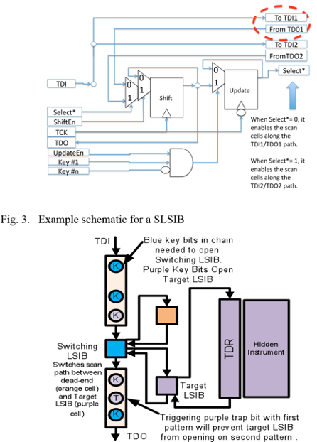
From the attacker’s viewpoint, this means that he must start applying two-pattern tests. Each initial guess could have opened a SLSIB, but as long as both the dead-end cell and the target LSIB are set to receive the same data on CaptureDR, the attacker doesn’t know if he made a switch. The attacker must scan in an initial guess and perform an UpdateDR. He must then scan in a second pattern, which may possibly open an LSIB if the SLSIB was switched for the first pattern, and check the chain length. If unsuccessful, he must execute a network reset (to clear any Trap bits) and try again. In some ways, this is similar to the cost of a hierarchical scan structure where two LSIBs must be opened in sequence for hidden instrument access. For a scan chain of length n (including the one-bit dead end), the cost of a guess with this SLSIB architecture is:
Cost of guessLSIB_behind_SLSIB = 15+3n+d (11)
However, deterministically opening the SLSIB repeatedly on each try is not possible because opening the SLSIB provides no information to the attacker. A random guess must be used for both patterns every time. The expected cycles to unlock the target LSIB is:
Expected Time(unlock LSIB behind SLSIB) =
(15+3n+d)(2k1+k2+t+2) (12)
Here, k1 refers to the number of key bits required to switch the SLSIB, k2 refers to the number of key bits required to unlock the target LSIB behind it, and t refers to the number of Trap bits that may be set with the first UpdateDR that would prevent the target LSIB from opening. Note that both key sizes are in the same exponent. The time required as a function of key size and the number of traps grows as:
TimeRequiredGrowthRateSLSIB= O(k1+k2+t)=2k1+k2+t+2 (13)
In the alternative hierarchical case described in [1], where either key bits or a second LSIB lie behind the first LSIB, because the attacker can see the effect of the first LSIB opening, once he finds the LSIB, he can find the key bits for it with the method described in [1]. He can then deterministically open it on each new guessing attempt. (Of course, it could also be a honeytrap, and he could try both approaches.) Thus, the opening of each LSIB can be considered separately. For example, assume that 3 key bits are associated with the first LSIB and 10 key bits (and no traps) are associated with the second. On average, it will take 24 guesses to successfully open the first LSIB. (It is 24 instead of 23 because the LSIB itself must be set to the correct value.) Once the first LSIB is opened, it can be deterministically opened on additional guesses. Opening the second LSIB is expected to take an additional 211 guesses on average. Growth rate in expected time as a function of key size and number of traps is:
TimeRequiredGrowthRatehier=O(k1+k2+t) =2k1+1+2k2+t+1 (14)
The distribution of keys between the two LSIBs in the SLSIB case is irrelevant with respect to the expected total time as long as the overall chain contains enough non-key bits; only the total number of keys and traps matters. Thus, the key bits can be easily distributed between both LSIBs. In contrast, if the keys are distributed equally between the two LSIBs in the hierarchical case, the total expected time to access the hidden instrument will be much less than in the SLSIB case because the two exponentials are added together in Equation (14) instead of multiplied, as in Equation (13). This can be alleviated somewhat by having a more lopsided distribution of the key bits between the 2 LSIBs. The SLSIB is also better than a single LSIB with the same number of key bits. Each SLSIB requires at least one additional pass through the chain and state machine on each guess, and the same physical keybits can be reused on multiple passes (with different key values). Furthermore, if the attacker is not aware that SLSIBs are a possibility and only applies one-pattern tests interspersed with resets, he will never open the LSIB behind the SLSIB. His attack can be made even more difficult by cascading an arbitrary number of multiple SLSIBs behind each other such that he does not know how many patterns are needed. Finally, if Trap Bits associated with the target LSIB are present in the original chain, then scanning through that chain multiple times with different patterns will provide multiple opportunities to trip each of the traps when SLSIBs are cascaded.
V. RESULTS
We investigated multiple variations of the proposed optimizations. First, we compared HT and NO LSIBs in the case where either two HT or two NO LSIBs were present. In both cases, it was assumed that the number of key bits for the HT and NO LSIBs was very small, and the attacker will find them quickly. Thus, the primary cost of guessing and the expected time to find the target LSIB is dominated by the time spent after the discovery of the HT and NO LSIBs. This data is shown in Table 1. The k and t values refer to the number of key and trap bits related to opening the target LSIB. The value of d is 25. It is assumed that both HTLSIBs must be open or both NO LSIBs must be closed to open the target. The time to open the target LSIB is longer when NO LSIBs are present because the chain length on reset is longer.
TABLE I. COST OF EACH GUESS AND EXPECTED TIME TO OPEN TARGET LSIB AFTER BOTH HT / NO LSIBS ARE FOUND; 10 MHZ SCAN RATE
| k | t | N | m | j | Guess cost after both HT found (cycles) | Guess cost after both NO found (cycles) | E[time] HT (years) | E[time] NO (years) |
| 16 | 1 | 1280 | 128 | 128 | 16672 | 17440 | 2.77E-5 | 2.90E-5 |
| 16 | 1 | 1280 | 10 | 10 | 15610 | 15670 | 2.59E-5 | 2.60E-5 |
| 32 | 1 | 2560 | 128 | 128 | 32032 | 32800 | 3.49 | 3.57 |
| 32 | 1 | 2560 | 10 | 10 | 30970 | 31030 | 3.37 | 3.38 |
| 64 | 1 | 5120 | 128 | 128 | 62752 | 63520 | 2.93E10 | 2.97E10 |
| 64 | 1 | 5120 | 10 | 10 | 61690 | 61750 | 2.88E10 | 2.89E10 |
TABLE II. TOTAL TIME TO FIND HIDDEN INSTRUMENT USING EITHER ONE HIERARCHICAL LSIB OR ONE SLSIB; 10 MHZ SCAN RATE
| k1 | k2 | t | N | m | Total E[time] hierarchical (years) | Total E[time] SLSIB (years) | %incr SLSIB over hier |
| 1 | 15 | 1 | 1280 | 1 | 2.70E-6 | 6.45E-6 | 139% |
| 8 | 8 | 1 | 1280 | 1 | 3.58E-8 | 6.45E-6 | 1.79E4% |
| 15 | 1 | 1 | 1280 | 1 | 5.50E-7 | 6.45E-6 | 1.07E3% |
| 1 | 31 | 1 | 2560 | 1 | 3.51E-1 | 8.41E-1 | 140% |
| 16 | 16 | 1 | 2560 | 1 | 1.29E-5 | 8.41E-1 | 6.53E6% |
| 31 | 1 | 1 | 2560 | 1 | 7.02E-2 | 8.41E-1 | 1.10E3% |
| 1 | 63 | 1 | 5120 | 1 | 3.00E9 | 7.20E9 | 140% |
| 32 | 32 | 1 | 5120 | 1 | 1.68E0 | 7.20E9 | 4.29E11% |
| 63 | 1 | 1 | 5120 | 1 | 6.01E8 | 7.20E9 | 1.10E3% |
Next, we performed a comparison of the SLSIB and the case where a single hierarchical LSIB must be opened for a target LSIB to be found. Only a single scan cell is present behind the hierarchical LSIB. Thus, the hardware cost of the two approaches is similar, and the difference arises from the feedback the attacker receives. In this experiment, we assume the attacker will treat the first LSIB in the hierarchical case as a single HTLSIB. In Table 2, k1 refers to the number of key bits for the hierarchical LSIB/SLSIB, and k2 and t refer to the number of key and trap bits associated with the target LSIB. The distribution of key bits has no effect in the switching LSIB case, but it has a dramatic effect on the hierarchical case. An even distribution of key bits yields the worst possible time in the hierarchical case because two smaller exponentials are added. Furthermore, the existence of a trap bit in the chain affecting the target LSIB means that when the key bits are distributed in a skewed fashion that it is advantageous to have more key bits in k2 because the effect of the trap bit is magnified with the larger exponential. In all cases, the switching LSIB was better—sometimes by a huge amount.
VI. CONCLUSIONS
In this paper we have presented several techniques that can significantly increase the cost an attacker faces when trying to investigate an IEEE P1687 network containing LSIBs. Although they will not prevent all possible attackers, they can make it less likely that all but the most dedicated attackers will find the hidden instruments by scanning data through the network while using the studied attack modes.
In a real scan network, parts of the network not intended to be secure will be documented in P1687 PDL and ICL. If an attacker has access to this documentation, he may be able to use it to find the initial chain length as well as the location of non-locking SIBs. Hidden features should not be included. Thus, we are also investigating how to document the security features of the design in an encrypted format that can’t easily be read by an attacker as as well additional protection schemes to protect data transferred from the tester to the chip inputs. Finally, note that in this paper’s analysis, attack success merely corresponds to finding a target LSIB. An attacker will still need to do additional work to determine what lies behind each LSIB and how it works. The total amount of time that needs to be spent by an attacker is even greater than that shown here.
VII. REFERENCES
[1] Jennifer Dworak, Al Crouch, John Potter, Adam Zygmontowicz, and Micah Thornton, “Don’t Forget to Lock your SIB: Hiding Instruments using P1687,” in Proceedings of the IEEE International Test Conference, 2013.
[2] D. Mukhopadhyay, S. Banerjee, D. Roychowdhury, and B. B. Bhattacharya, “CryptoScan: A Secured Scan Chain Architecture,” Test Symp. 2005 Proc. 14th Asian, pp. 348–353, 18.
[3] A. A. Kamal and A. M. Youssef, “A Scan-Based Side Channel Attack on the NTRUEncrypt Cryptosystem,” Availab. Reliab. Secur. ARES 2012 Seventh Int. Conf. On, pp. 402–409, 20.
[4] Bo Yang, Kaijie Wu, and R. Karri, “Scan based side channel attack on dedicated hardware implementations of Data Encryption Standard,” Test Conf. 2004 Proc. ITC 2004 Int., pp. 339–344, 26.
[5] R. F. Buskey and B. B. Frosik, “Protected JTAG,” Parallel Process. Workshop 2006 ICPP 2006 Workshop 2006 Int. Conf. On, p. 8 pp.–414, 2006.
[6] C. J. Clark, “Anti-tamper JTAG TAP design enables DRM to JTAG registers and P1687 on-chip instruments,” Hardw.-Oriented Secur. Trust HOST 2010 IEEE Int. Symp. On, pp. 19–24, 2010.
[7] K. Rosenfeld and R. Karri, “Attacks and Defenses for JTAG,” Des. Test Comput. IEEE, vol. 27, no. 1, pp. 36–47, Feb. 2010.
[8] L. Pierce and S. Tragoudas, “Enhanced Secure Architecture for Joint Action Test Group Systems,” Very Large Scale Integr. VLSI Syst. IEEE Trans. On, vol. PP, no. 99, pp. 1–1, 2012.
[9] J. Lee, M. Tehranipoor, C. Patel, and J. Plusquellic, “Securing Designs against Scan-Based Side-Channel Attacks,” Dependable Secure Comput. IEEE Trans. On, vol. 4, no. 4, pp. 325–336, Dec. 2007.
[10] J. Lee, M. Tehranipoor, C. Patel, and J. Plusquellic, “Securing Scan Design Using Lock and Key Technique,” in Defect and Fault Tolerance in VLSI Systems, 2005. DFT 2005. 20th IEEE International Symposium on, 2005, pp. 51–62.
[11] R. Nara, H. Atobe, Youhua Shi, N. Togawa, M. Yanagisawa, and T. Ohtsuki, “State-dependent changeable scan architecture against scan-based side channel attacks,” Circuits Syst. ISCAS Proc. 2010 IEEE Int. Symp. On, pp. 1867–1870, May 2010.
[12] G. Sengar, D. Mukhopadhyay, and D. R. Chowdhury, “Secured Flipped ScanChain Model for Crypto-Architecture,” Comput.-Aided Des. Integr. Circuits Syst. IEEE Trans. On, vol. 26, no. 11, pp. 2080–2084, Nov. 2007.
[13] Y. Atobe, Youhua Shi, M. Yanagisawa, and N. Togawa, “Dynamically changeable secure scan architecture against scan-based side channel attack,” SoC Des. Conf. ISOCC 2012 Int., pp. 155–158, 4.
[14] S. Paul, R. S. Chakraborty, and S. Bhunia, “VIm-Scan: A Low Overhead Scan Design Approach for Protection of Secret Key in Scan-Based Secure Chips,” VLSI Test Symp. 2007 25th IEEE, pp. 455–460, 6.
[15] J. Da Rolt, G. Di Natale, M.-L. Flottes, and B. Rouzeyre, “Are advanced DfT structures sufficient for preventing scan-attacks?,” VLSI Test Symp. VTS 2012 IEEE 30th, pp. 246–251, Apr. 2012.
[16] Suresh Goyal, Michele Portolan, and Bradford Van Treuren, “Patent Application: Method and apparatus for providing scan chain security,” US 20110314514A1.
[17] I. S. Kim and M. H. Kim, “Agent-based honeynet framework for protecting servers in campus networks,” Inf. Secur. IET, vol. 6, no. 3, pp. 202–211, Sep. 2012.